caMPike, I've sent you a PM with more details.
Looking to buy or sell a Marco Polo? You can now advertise from just £9.99 Click Here
You are using an out of date browser. It may not display this or other websites correctly.
You should upgrade or use an alternative browser.
You should upgrade or use an alternative browser.
Sure Norcis, I'll send you the same details I sent Campike.MarioF, could you share more details with me?
Sure gcomtet, I'll send you a PM.MarioF could you please send me détails of your installation thx
Rob & Sandra
Member
Hi MarioF. I’d also welcome information as just looking at swapping leisure battery system
MarioF, could you please send me details too.
I am about to get a DC-DC charger and Lifepo4 battery. My installers have not decided where to put the charger yet (they hope to reuse the existing high-current cabling).
A german company who do this work for MPs say on their site it goes under the seat but there might be a confusion over left and right hand drive so your experience may help with what is possible.
This is the info I sent Campike.
As I said, the install consists of two 175w solar panels mounted onto aluminium strips with pop rivets. These in turn were screwed onto the roof using the roof rack channel with some rectangular bolts and torx screws.
The cable went in through the rear door rubber at the top right, I made a little slit and passed it through, then along the top of the interior behind the top air vents (these are easy to remove) and down the post directly behind the passenger seat which hold the seat belts, again easy to remove. This leaves the cable directly behind the passenger seat.
The LifePo4 battery went into the same spot as the original battery. The new battery is ever so slightly wider than the original and a subtle hammering widened the lower battery support rails to accommodate the new battery. I also had to cut the plastic top support so that this didn't interfere with the battery communication ports. The battery went home very snugly, very pleased with the way it fitted.
The Renogy battery is a tight fit height wise but this battery has the advantage that it can be turned off and on via a special switch supplied. So this facilitates the installation and cabling up of the battery while it's turned off. Once in place it can be turned on and the bluetooth (optional) device attached. You can also attach the bluetooth to the DC charger and get more/different info.
I installed the DC controller directly behind the leisure battery on the other side of the steel panel, drilling some holes by which to pass the cables. Make sure you buy decent quality and gauge cable.
I bypassed the relay that comes from the starter battery to the leisure battery mentioned in the original post as the DC charger takes care of charging the leisure battery first then charging the starter battery once the leisure battery has been charged. It also isolates the starter battery from the leisure battery.
To get the DC controller in I had to remove a small portion of carpet so that there would be enough ventilation and space to "hang" the DC charger. It's tight but fits and is screwed to the steel panel separating the battery.
I once left the van 5 days with the fridge turned on, when I got back from my ride the battery showed 96% charge. I have seen that that the fridge uses about 10-15% over night but this is replenished the next day with ease. I'm thinking of installing a 12v hot water heater to make use of the surplus power.
Please bear in mind that my MP is LHD & 2008.
The rear overhead cupboard with the speakers has a small screw to the right and a long screw to the left accesible from inside the cupboard, this screw is also the coat-hanger. To the rear it has some clips. You don't need to take this out completely. I also removed the rear buttons for the suspension control and moved the cover of the rear post to be able to put my hand / arm up inside.
For the air vents just unscrew them and slide them out to one side. On the B-Post unscrew the seat belt from the top and then just work the cover away from the rubber seal on the door. The bottom plastic has square clips moulded on the rear, just ease the plastic up and then out.
Image14: detail of torx bolts into rectangle nuts within the channel, these were threadlocked.
Image18: coat hanger bolt accesible from within the rear cubboard.
Image10: slit cut into rear flex rubber.
Image13: detail of wiring from solar panels, cable tied to last aluminium strip, note the inline fuse highlighted.
Image7: small screws that support the rear cubboard.
Image4: cable that was run down the B-Post.
Image3: Screen that plugs into the Renogy DC-DC controler.
Image2: fuses from alternator & lithium battery.
Image1: Renogy controller, note cut out below where I removed some carpet. (saved it and it can be reinstalled if need be)
Image5: remove vents & light to pass cables to the B-Post.
Image15: detail of the battery support I cut that stopped the battery fron inserting fully due to the comunication ports on the battery. Note the BT-2 bluetooth connected as pictured in image 17.
Image16 : The battery is a tight fit hight wise but can be turned on or off via a special switch supplied and connected to the comunication port as depicted in image 15.
Image17: general view of the battery, note it's held into place with the end lug, hight of the battery and BT-2 bluetooth device for linking to phone app. This device could also be connected to the DC-DC controller for more different info.
That's about it, hope it helps.
Any questions, just ask and let me know if you go ahead and install. I took me 2 days, one for roof top solar panel mount and another for the battery and controler install.
Good luck.
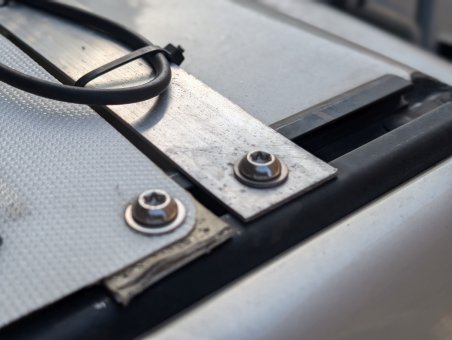
image014.jpg
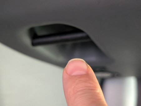
image008.jpg
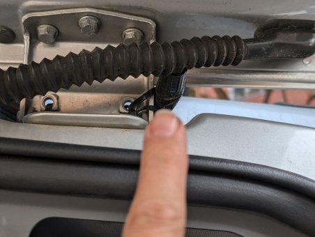
image010.jpg
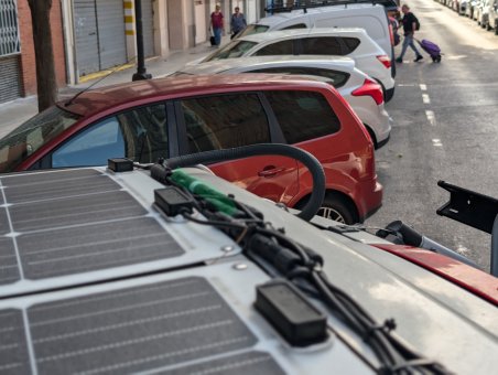
image013.jpg
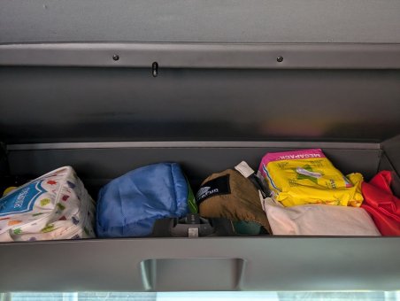
image007.jpg
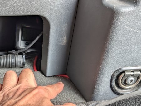
image004.jpg
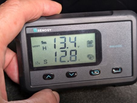
image003.jpg
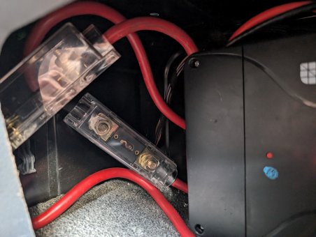
image002.jpg
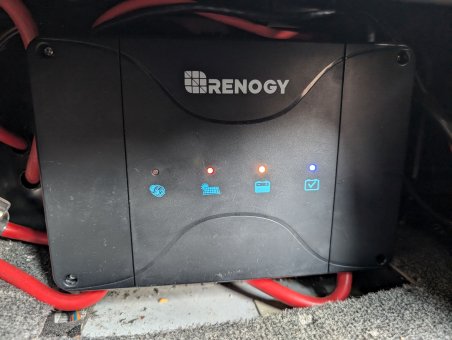
image001.jpg
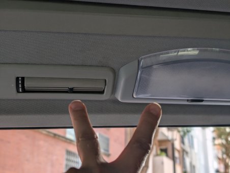
image005.jpg
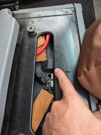
image015.jpg
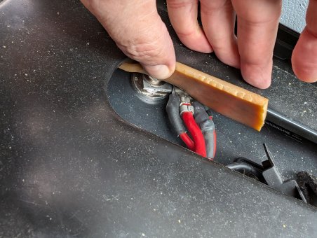
image016.jpg
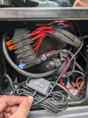
image017.jpg
I can't stress that the battery you install should be of good quality.
After investigation, the Renogy kit in general is very well built.
You can find a review on youtube about the battery here:
 eu.renogy.com
As I said, the install consists of two 175w solar panels mounted onto aluminium strips with pop rivets. These in turn were screwed onto the roof using the roof rack channel with some rectangular bolts and torx screws.
The cable went in through the rear door rubber at the top right, I made a little slit and passed it through, then along the top of the interior behind the top air vents (these are easy to remove) and down the post directly behind the passenger seat which hold the seat belts, again easy to remove. This leaves the cable directly behind the passenger seat.
The LifePo4 battery went into the same spot as the original battery. The new battery is ever so slightly wider than the original and a subtle hammering widened the lower battery support rails to accommodate the new battery. I also had to cut the plastic top support so that this didn't interfere with the battery communication ports. The battery went home very snugly, very pleased with the way it fitted.
The Renogy battery is a tight fit height wise but this battery has the advantage that it can be turned off and on via a special switch supplied. So this facilitates the installation and cabling up of the battery while it's turned off. Once in place it can be turned on and the bluetooth (optional) device attached. You can also attach the bluetooth to the DC charger and get more/different info.
I installed the DC controller directly behind the leisure battery on the other side of the steel panel, drilling some holes by which to pass the cables. Make sure you buy decent quality and gauge cable.
I bypassed the relay that comes from the starter battery to the leisure battery mentioned in the original post as the DC charger takes care of charging the leisure battery first then charging the starter battery once the leisure battery has been charged. It also isolates the starter battery from the leisure battery.
To get the DC controller in I had to remove a small portion of carpet so that there would be enough ventilation and space to "hang" the DC charger. It's tight but fits and is screwed to the steel panel separating the battery.
I once left the van 5 days with the fridge turned on, when I got back from my ride the battery showed 96% charge. I have seen that that the fridge uses about 10-15% over night but this is replenished the next day with ease. I'm thinking of installing a 12v hot water heater to make use of the surplus power.
Please bear in mind that my MP is LHD & 2008.
The rear overhead cupboard with the speakers has a small screw to the right and a long screw to the left accesible from inside the cupboard, this screw is also the coat-hanger. To the rear it has some clips. You don't need to take this out completely. I also removed the rear buttons for the suspension control and moved the cover of the rear post to be able to put my hand / arm up inside.
For the air vents just unscrew them and slide them out to one side. On the B-Post unscrew the seat belt from the top and then just work the cover away from the rubber seal on the door. The bottom plastic has square clips moulded on the rear, just ease the plastic up and then out.
Image14: detail of torx bolts into rectangle nuts within the channel, these were threadlocked.
Image18: coat hanger bolt accesible from within the rear cubboard.
Image10: slit cut into rear flex rubber.
Image13: detail of wiring from solar panels, cable tied to last aluminium strip, note the inline fuse highlighted.
Image7: small screws that support the rear cubboard.
Image4: cable that was run down the B-Post.
Image3: Screen that plugs into the Renogy DC-DC controler.
Image2: fuses from alternator & lithium battery.
Image1: Renogy controller, note cut out below where I removed some carpet. (saved it and it can be reinstalled if need be)
Image5: remove vents & light to pass cables to the B-Post.
Image15: detail of the battery support I cut that stopped the battery fron inserting fully due to the comunication ports on the battery. Note the BT-2 bluetooth connected as pictured in image 17.
Image16 : The battery is a tight fit hight wise but can be turned on or off via a special switch supplied and connected to the comunication port as depicted in image 15.
Image17: general view of the battery, note it's held into place with the end lug, hight of the battery and BT-2 bluetooth device for linking to phone app. This device could also be connected to the DC-DC controller for more different info.
That's about it, hope it helps.
Any questions, just ask and let me know if you go ahead and install. I took me 2 days, one for roof top solar panel mount and another for the battery and controler install.
Good luck.

image014.jpg

image008.jpg

image010.jpg

image013.jpg

image007.jpg

image004.jpg

image003.jpg

image002.jpg

image001.jpg

image005.jpg

image015.jpg

image016.jpg

image017.jpg
I can't stress that the battery you install should be of good quality.
After investigation, the Renogy kit in general is very well built.
You can find a review on youtube about the battery here:
Renogy EU Official | Trusted Energy Solutions
Renogy offers premium solar panels, inverters, lithium batteries, and solar charge controllers for off-grid solar systems in the EU. Shop with confidence for top-quality products, expert guidance, and exceptional customer support to meet your energy requirements.

